

Home > Resources > Technical Guides > Stainless Steel Technical Guide > Ferrite In Austenitic Stainless Steel Weld Metal
Stainless Steel Technical Guide
View technical guides for guidance on welding various metals and selecting the right Hobart Brothers filler metal solution for your application.
Stainless Steel Technical Guide
Ferrite In Austenitic Stainless Steel Weld Metal
What’s so formidable about ferrite? It’s not so formidable, it just makes things “tough”. The structure of austenitic stainless steel weld metals varies from fully austenitic, as in 310, to dual phase austenitic-ferritic, as in 308, 309, 312, 316 etc., which contain a small volume of the ferrite phase. In most cases, some ferrite is desired for crack resistance. The extent of the ferrite phase depends mainly on composition, but for a given analysis will increase with the rate of cooling from elevated temperatures. For example, a 20CR, 10Ni alloy cooled through the temperature range of about 2550 to 1850°F will contain more ferrite at room temperature if cooled rapidly as in welding than if cooled slowly as in casting.
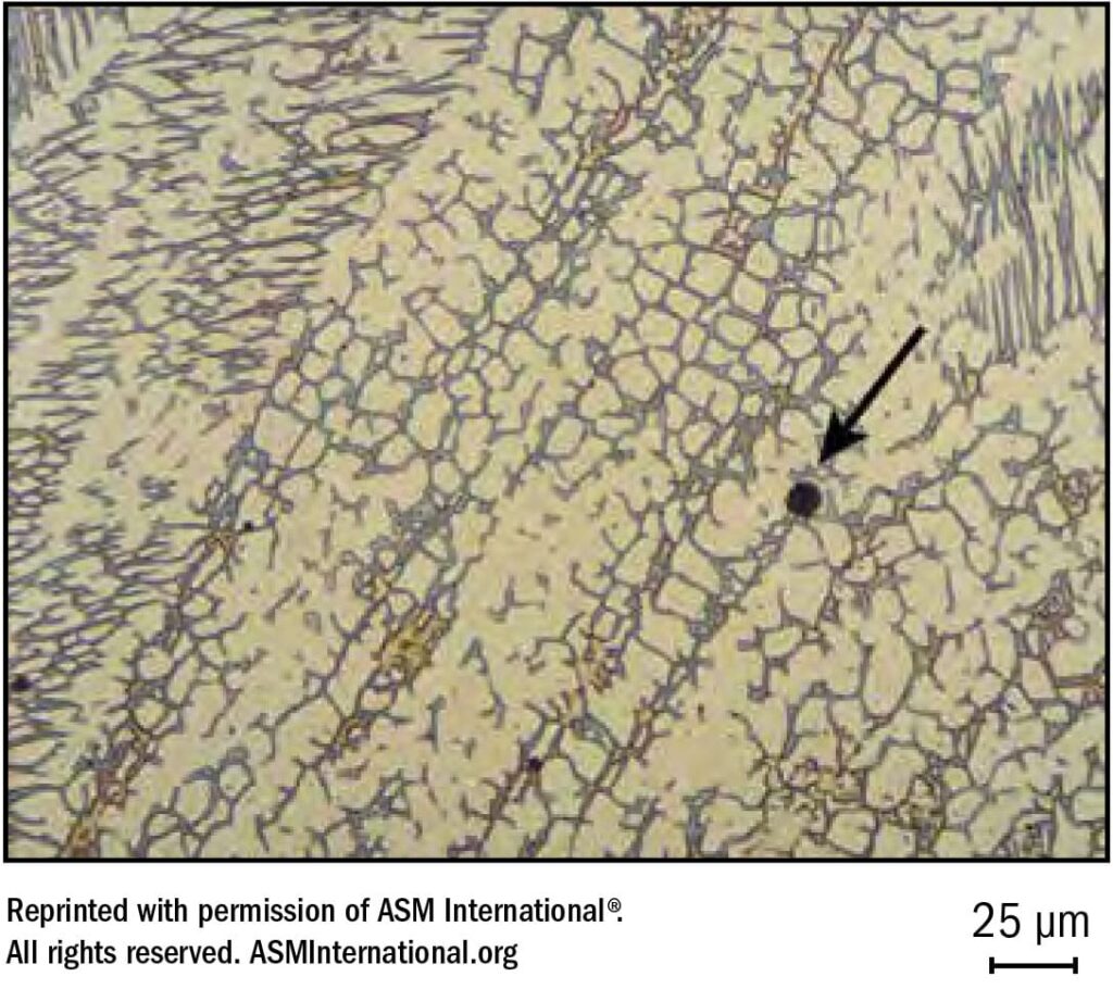
Microfissuring and cracking can occur when low temperature melting compounds of P, S, Si, and Cb or other tramp elements tend to segregate intergranularly, thus setting the stage for hot cracking. Since these low melting compounds are much more soluble in ferrite than is austenite, a small amount of ferrite can “absorb” significant quantities of the impurities and reduce segregation to grain boundaries. With relatively small amounts of ferrite these boundaries are discontinuous, thus interrupting any cracking paths. Therefore, resistance to cracking can be enhanced by inducing the formation of ferrite in what might otherwise be a fully austenitic weld deposit. See Figure 25.
Frightful Ferrite?
Is ferrite always desirable? Ferrite can get you into trouble in some areas. In molybdenum-bearing grades like 316 and 317 and their L versions, ferrite can cause a major decrease in corrosion resistance in hot oxidizing media (e.g. urea). In cryogenic applications the low temperature impact strength decreases with increasing ferrite. A closely balanced FN is required to ensure adequate crack resistance and good low temperature impact strength. Above about 10FN there is danger of ferrite (which contains some Cr in solid solution) transforming to brittle sigma phase when the service temperature is in the 1000-1650°F range. In some multipass welds the exposure to the heat of welding alone may produce sigma phase in high ferrite welds. For elevated temperature service, 309L, with a relatively low FN would be preferred. The effect of adding Mo to the latter would promote sigma and some chi phases at elevated temperatures but would increase crack resistance at normal temperatures.
Determination of Ferrite Level
The ferrite content in austenitic stainless steel weld metal can be controlled by varying the composition. Chromium promotes ferrite formation while nickel opposes it. Other elements with varying degrees of potency act in the same manner as either chromium or as nickel. Thus we have a chromium equivalent (ferritizers) vs. a nickel equivalent (austenitizers). With known composition we can add up the ferritizers vs. the austenizers, using the guidelines of the DeLong diagram (Figure 26) and plot these two values on the diagram to establish the calculated ferrite anticipated in the weld deposit. Note that the actual deposit ferrite may drop about 1 FN for GTAW and about 4 FN for GMAW because of pick-up of N where gas coverage is inadequate.
It must be recognized that the Welding Research Council (WRC) Delong diagram is an empirical device developed mainly around common welding alloys of the 1960s and early 1970s. The diagram may not be accurate when compositions depart appreciably from the common welding alloys of that period. Considerable evidence exists that Mn at high levels (above 2%) does not act as an austenitizer, so the diagram tends to underestimate ferrite in high Mn weld metals. There is also some evidence that, for alloys at the rich extremes of Type 309 and beyond, the diagram tends to over-estimate ferrite. Whenever possible, direct measurement of ferrite is preferable to estimates using the diagram. Nevertheless, the diagram continues to be a useful tool so long as its limitations are understood.
A predictive diagram for ferrite in stainless steels that is considered more accurate than either of the Schaeffler or DeLong diagrams has been developed. See Figure 26 and Welding Research Supplement Page 289-S Welding Journal December, 1988.
Ferrite is magnetic and austenite is not, so the magnetic attraction is directly proportional to the amount of ferrite present. The WRC Ferrite Number (FN) system is generally accepted as the best method for measuring and specifying ferrite content in austenitic stainless steel weld metals. They abandoned the notion of defining a volume percent ferrite for weld metal in favor of an arbitrary scale of Ferrite Number (FN).
The FN scale is defined by a set of National Bureau of Standards coating thickness standards. Each thickness of non-magnetic plating over a magnetic substrate is assigned an FN and a series of these standards is used to develop a calibration procedure. The basic instrument of the WRC FN system is a Magne-Gage which uses a small magnet that is pulled from the specimen by a spring force. The spring force is related to the FN by the calibration line using a “white dial” scale on the instrument.
The white dial scale on a Magne-Gage has 100 divisions and is usually calibrated by the manufacturer so that a little more than one revolution of the white dial scale covers the range of 0-28 FN with the #3 magnet. The white dial readings decrease as the FN increases so that 0 FN usually corresponds to a WD greater than 100 (e.g. 110). The Magne- Gage is very accurate but is not an all-position production tool.
An Inspector Gage gives a direct reading and can be used in all positions. The Severn Gage can be used in all positions but provides a bracket FN rather than a direct reading — the FN determined is more than one reading but less than another. The Ferritescope utilizes a magneto-inductive method to determine the permeability and hence the ferrite content of production welds.
How Much Ferrite Is Enough?
Excluding environments like urea or cryogenic applications, how much ferrite is enough? An aim of about 5-10 FN is good general practice to mitigate micro cracking and stress-corrosion cracking. The nuclear industry specifies 5FN minimum. Some say 2 FN is adequate, others that 3FN is required for multipass welds.
It should be noted that when welding with austenitic stainless steel covered electrodes in the vertical-up position the ferrite content in the deposit will likely be lower than when welding in the flat position. This may be due to the greater pick-up of nitrogen and greater carbon recovery coincident with vertical-up weaving technique.