
Home > Resources > Technical Guides > Stainless Steel Technical Guide > Tubular and Solid Stainless Steel Wires
Stainless Steel Technical Guide
View technical guides for guidance on welding various metals and selecting the right Hobart Brothers filler metal solution for your application.
Stainless Steel Technical Guide
Tubular and Solid Stainless Steel Wires
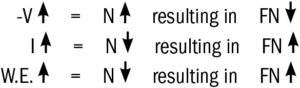
Increased voltage means a longer arc and a correspondingly larger volume of N-containing gas or plasma the metal must pass through; therefore, N increases and FN decreases. Increased current means higher wire feed speed rates; therefore, more metal per unit of time is passing through a given arc volume so that N is diluted by additional metal, resulting in N decreases and FN increases. Increased wire extension (stick-out) means decreased arc voltage (since part of the “fixed” voltage in a CV system is in the arc and part in the wire extension) and a shorter arc resulting in correspondingly smaller amounts of N and, consequently, an increase in FN.
These effects can be briefly expressed as follows:
Stainless steel wires are quite popular because of high operator appeal, good bead appearance and tie-in, and a cool arc compared with the G/S wires that are operated in inert gas. The ability to be used with these gases has solved the problems of the fabricator who is not permitted to use an “open arc” type cored wire or, because of poor parameter control or dilution is not producing satisfactory levels of ferrite in the weld deposit. If a shielding gas is used, CO2 is preferred for best operation but some C pick-up (up to about 0.01%) may be expected. Operation is fair with 75/25 argon-CO2 gas and unsatisfactory with gases of higher argon content.
Type XXXT0 and XXXT1 Wires
XXXT0 cored stainless steel wires are designed for flat and horizontal welding of stainless steel. XXXT1 wires are for out-of-position welding of stainless steel.
XXXT0 and XXXT1 wires require external gas shielding. Preferred gas is 75% argon – 25% CO2. 100% CO2 also be used. Do Not use 99-1 or 98-2 argon-oxygen gases.
T0 And T1 Operational Characteristics – Welding Parameters – Technique
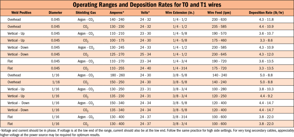
XXXT0 and XXXT1 wires used with Argon-CO2 shielding gas produce a spray-like transfer with no spatter at high currents (160 amperes or higher with 0.045 inch wire or 180 amperes or higher with 1/16 inch wire). At lower currents or in CO2 gases, a small ball transfer is produced. These wires, characterized by a dense and thick slag cover, operate satisfactorily over fairly wide current and voltage ranges. Optimum welding parameters are influenced by equipment, joint configuration, plate thickness, length of cables, quality of work connection, and operator skill. Suggested parameters, together with typical deposition rates, are shown in Figure 47. Deposition efficiency is typically 84-86%. A shielding gas flow rate of 25-35 CFH is suggested.
In the flat position, a number of welding techniques provide acceptable results. It should be noted that at high welding currents the spray transfer becomes so intense that the core of the wire extends out of the end of the wire into the arc. In this situation, it is important to adjust the welding voltage high enough that the core tip remains above the surface of the weld pool. If the wire core touches the weld pool, this will most likely cause slag entrapment in the weld pool, as evidenced by scattered slag indications in radiographs. However, when the voltage is set properly, the core tip is kept above the weld pool and excellent X-ray quality can be obtained.
In overhead welding, excessive electrical stick-out (contact tip to work distance) tends to cause the metal transfer to be a larger ball and excessive spatter may be noticeable to the extent that the shielding gas cup may become blocked. This effect is readily eliminated by maintaining a short stick-out. In fillet welds or tight grooves in the overhead position, adjust the contact tip so that it is nearly flush with the end of the gas cup.
In vertical-up welding, best results are usually obtained by directing the wire perpendicular to the joint. It is important to avoid contact between the gas cup and the slag cover below the arc because contact will cause the still partially molten slag to tear and allow the molten metal behind the slag dam to run out of the joint. To initiate a vertical-up weld bead, it is sometimes best to strike the arc slightly to the side of the weld centerline (perhaps 1/8 inch or more away) and begin weaving slightly. Once the slag starts to set up, you can run a stringer or weave as desired. A stringer is easier at lower currents in Argon-CO2.
In the vertical-up position, do not try to travel upward too fast. If you outrun the slag cover, you will drop the metal out of the joint. If you look over the gas cup at the weld puddle, you should see the slag-metal interface at the front edge of the puddle. If you cannot see the slag -metal interface, chances are you are traveling upward too fast and will get a sagging bead or a drop-out.
The minimum thickness that can be welded easily vertical-up is about four times the wire diameter. That is, for 0.045 inch wire, the minimum base metal thickness is 3/16 inch For 1/16 inch wire, the minimum base metal thickness is 1/4 inch.
Vertical-down welding is only suggested on material too thin for vertical- up welding. Spray transfer is better with higher voltage and rapid travel speed to prevent the puddle from overrunning the arc. A concave bead will result.
The best overhead technique involves no weave. A steady linear travel generally produces best results; low travel speed will produce excessive droop of the weld metal. A dragging torch angle (wire inclined perhaps 30° from perpendicular to the joint, directed back toward the solidifying weld bead) is generally optimum for bead shape.
Cladding of a vertical wall can be accomplished by two techniques. One is to stack horizontal fillet beads one atop the other up the face of the wall. The other is a vertical weave much like capping off the face of a groove weld. The vertical-up weave technique results in optimum surface profile when the weave is limited to about 1 inch in width.
In joining mild steel or low alloy steel to stainless steel in out-of- position welding, the same techniques work as those given for stainless- to-stainless joints. Removing the mill scale from the carbon or low alloy steel, especially in vertical-up welding, improves bead shape (flatness). If mill scale or rust is not removed, the iron oxide, when added to the XXXT0 and XXXT1 slag system, tends to make the slag more fluid and may result in a weld profile more convex than desired. Especially for vertical-up welding where penetration is higher, only high ferrite weld metal is recommended (grade 309LT1) because excess dilution tends to result in centerline cracking. When finishing a vertical-up joint of this type, it can be useful to run off the joint on the stainless side slightly to avoid crater cracks. Especially for a root pass, lower penetration with small ball transfer, rather than spray transfer, also helps to avoid cracking problems.
In any welding position, it should be noted that the slag of XXXT1 wires freezes much more quickly than the weld pool freezes. Because of this, the weld bead surface is generally almost free of ripples. This relationship of slag freezing temperature to weld metal freezing temperature is essential for out-of-position welding. In the flat position, or in horizontal fillets, the lack of ripple might be considered unappealing by some users. If a rippled surface is considered more attractive for flat or horizontal applications, then XXXT0 self-shielded flux cored wires might be preferred.
Weld metal deposited in the flat or horizontal position with XXXT0 wires will be sound, provided that high current-low voltage conditions are avoided. The conditions recommended for vertical-up or overhead welding are generally suitable for flat welding. If higher currents are desired for increased deposition rates, then 30 volts or more may be necessary to produce X-ray quality welds. At high currents, the core of the wire will be noted to protrude from the end of the wire by as much as 1/4 inch If this touches the bottom of the weld puddle, slag entrapment will result. Increased voltage keeps this from occurring.