


Troubleshooting Common Self-Shielded FCAW Problems
Self-shielded Flux Cored Arc Welding (FCAW) is a proven welding process for structural steel erection, heavy equipment repair, bridge construction, and ship and barge construction. It offers high deposition rates, a wide range of mechanical properties and good weldability among other desirable features and benefits. That doesn’t mean, however, that it’s free of challenges and difficulties. We’ll explore common pitfalls encountered during the normal course of self-shielded flux-cored arc welding, and trusted ways to correct them.
Wire Feed Problems: Birdnesting and Burnback
Easily one of the most common problems with flux-cored arc welding, especially on construction sites, wire feed stoppages and malfunctions are more than just an annoying source of down time. Birdnesting and burnback can prematurely extinguish the welding arc and create irregularities that may weaken the weld bead.Birdnesting is a tangle of wire that halts the wire from being fed.
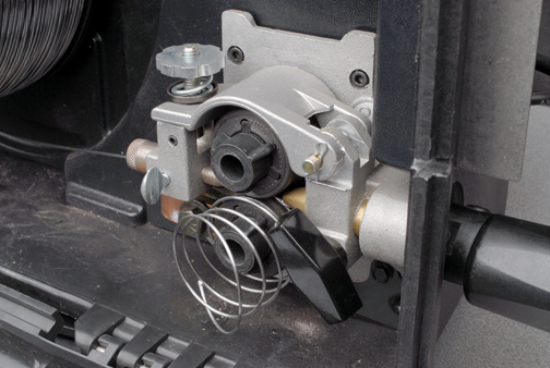
(as seen here) can be a frustrating source of downtime.
Fixing a Birdnest
Fix a birdnest by flipping up the drive roll and pulling the wire back out of the gun. Trim off the affected wire and re-thread it through the feeder and back to the gun. Incorrect drive rolls, tension settings, blockages in the liner, improperly trimmed liners (too short/burred/pinched) or the wrong liner (too small or large for the electrode diameter) are all sources of birdnesting.
FCAW wire is a tubular consumable and therefore is much softer then GMAW solid wire. The correct drive rolls for FCAW wire are knurled V groove drive rolls. With the correct drive roll, the correct tension must also be used. Too much tension will flatten the wire and will not allow the wire to feed through the contact tip. This is considered a birdnest. To set the proper tension, a good technique is to start by releasing the tension on the drive rolls. Increase the tension while feeding the wire into the palm of your welding glove and continue to increase the tension one half turn past wire slippage. Blockages in the liner can also cause birdnesting. Replace the liner if you find a blockage. Always trim the liner according to the manufacturer’s direction. Additionally, make sure you are using the correct size liner for your electrode.
Burnback is the formation of a weld in the contact tip that occurs when the wire feed speed is too slow or if the gun is held too close to the workpiece. Correcting this problem is easy: increase wire feed speed and the distance of the gun from the workpiece (the contact tip should be no further than 1 1/4-in. from the metal). Also remember to replace the contact tip if burnback occurs.
Porosity and Wormtracking
Porosity is a small pocket of gas caught in the weld metal. This can appear at any specific point on the weld or along its full length. This discontinuity—whether internal or on the surface of the weld bead—significantly weakens the structural integrity of any weld.
A dirty workpiece also causes porosity. Clean the surface of the base metal toremove rust, grease, paint, coatings, oil, moisture and dirt prior to welding. You can also use filler wire with added deoxidizers to “clean” the weld.
both outcomes of too much voltage.
Additional causes of porosity include welding wire that extends too far from the contact tip (the wire should extend no more than 1 1/4-in. beyond the contact tip). Impurities in the base metal, such as sulfur and phosphorous in steel, can be a further cause or porosity, remedied by changing the base metal to a different composition (where specifications allow).
Worm tracking are marks on the surface of the weld bead. These marks are caused by the gas that is created by the flux in the core of the wire. The gas causes worm tracking when there is excessive voltage for a given wire feed setting/amperage. To prevent worm tracking, use the manufacturer’s recommended parameters for a given wire diameter. If worm tracking does occur, reduce your voltage by increments of one-half volt until the worm tracking is eliminated.
Slag Inclusions
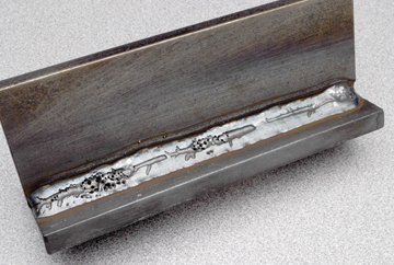
Slag is a naturally occurring part of flux-cored welding. This occurs when the molten flux from the core of the wire solidifies on top of the weld. These inclusions occur when the slag gets trapped inside of the weld metal. This creates the potential for weakened weld components and reduced serviceability. These inclusions can be caused by incorrect weld bead placement, incorrect travel angle, low heat input, or poor interpass cleaning.
Weld bead placement is critical when making multiple passes on thick sections of metal. This is especially important on the root passes of plug welds or wide v-groove openings. Careful consideration must be paid to providing sufficient space in the weld joint for additional passes, particularly on root joints requiring multiple passes.The travel angle of self-shielded FCA welding can also cause slag inclusions. Generally, if slag inclusions are caused by incorrect travel angle, you should increase your drag angle.
In the flat, horizontal, and overhead positions your drag angle should be between 15 and 45 degrees. In the vertical up position, your drag angle should be between 5 and 15 degrees. To low of welding heat input may also cause slag inclusions. Always use the manufactures recommended parameters for a given wire diameter. If slag inclusions still occur, increase the voltage until the inclusions cease.
Undercutting and Incomplete Fusion
Undercutting occurs when a groove melts in the base metal next to the toe of the weld and is not adequately filled by the weld metal. This discontinuity creates a weaker area at the toe of the weld and could cause cracking. To correct this problem, reduce the welding current, decrease the welding arc voltage and adjust your electrode angle as needed. Reduce travel speed so that the weld metal completely fills the melted-out areas of the base metal and/or pause at each side of the weld bead when using a weaving technique.
a beveled joint can greatly reduce the chance of incomplete
penetration.
Incomplete Fusion
Incomplete fusion (or lack of fusion) is the failure of the weld metal to fuse completely with the base metal or the preceding weld bead in multi-pass applications. Incorrect electrode/work angles that cause the weld metal to get ahead of the arc can be the culprit and should be adjusted accordingly. For proper welding angles follow these steps: To prevent incomplete fusion, place the stringer bead in its proper location at the joint, adjusting the work angle or widening the groove to access the bottom during welding. Keep the arc on the trailing edge of the welding puddle and remember to use a correct gun angle drag of 15 to 45 degrees. If using a weaving technique, momentarily hold the arc on the groove sidewalls when welding.
If correcting the electrode/work angle does not remedy the problem, check to see if the electrode is getting ahead of the welding puddle. Simple adjustments, such as increasing travel speed or using a higher welding current, will correct the problem.
A dirty workpiece could also be the cause of the problem. Always clean the surface of the base metal prior to welding to remove contaminants. If you suspect insufficient heat input could be contributing to incomplete fusion, select a higher voltage range and/or adjusting the wire feed speed as necessary.
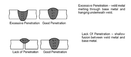
Excessive Penetration / Lack of Penetration
Excessive penetration occurs when the weld metal melts through the base metal and hangs underneath the weld. This is often caused by excessive heat input. To correct the problem, select a lower voltage range, reduce wire feed speed and increase travel speed.
Lack of penetration is the shallow fusion between the weld metal and the base metal. An obvious cause (and exact opposite of excessive penetration) is insufficient heat input. Selecting a higher wire feed speed, a higher voltage range and/or reducing travel speed are viable remedies. Lack of penetration can also be caused by improper joint preparation and/or from the material being too thick. Joint preparation and design must permit access to the bottom of the groove. This also allows you to maintain proper welding wire extension and arc characteristics.
Final Considerations
Quality self-shielded FCA welds are the result of good welding technique, the proper choice of parameters and the welder’s ability to identify a problem quickly and rectify it. Armed with some basic information, you can aggressively tackle the most common problems associated with self-shielded FCA welding without sacrificing time or quality.