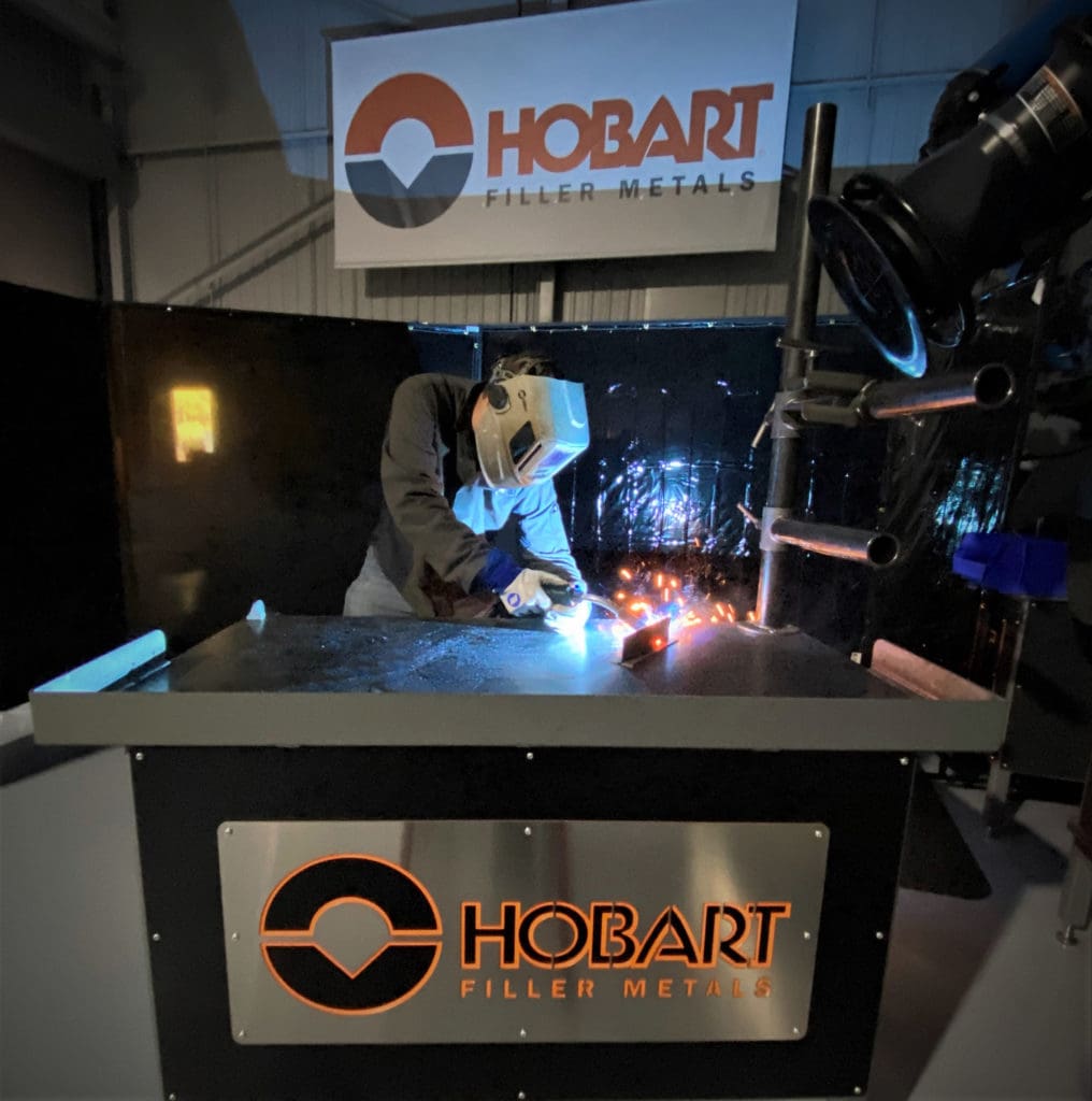
Tips for Setting MIG Welding Parameters for Thin Materials
Material thicknesses in fabrication and manufacturing can vary widely according to the application — and each has its own intricacies when it comes to MIG welding it.
Thinner materials, in particular, pose some unique challenges. From the potential for distortion to the risk of burnthrough and more, it’s easy to make mistakes. That’s why it’s important to have a solid understanding of proper welding parameters to ensure good weld quality and productivity.
So, what is considered thin material and where is it used most?
The American Welding Society (AWS) defines it as 3/16 inch or thinner in its AWS D1.3/D1.3M: 2018 Structural Welding Code – Sheet Steel.

Thin materials, such as basic carbon steel, are often used in automotive frames and panels, consumer goods, light structural components and ancillary connections.
As when welding other materials, getting the best results with thin materials depends on correct voltage, amperage and travel speed — along with other factors.
Common mistakes and consequences
Improper heat input is among the biggest culprits when it comes to problems with welding thin materials. High heat input can be caused by an excessive voltage or amperage setting, too slow a travel speed and/or needlessly long welds — and each can lead to burnthrough. Distortion, which occurs when the material expands and contracts as a result of welding and subsequent cooling, can also be amplified by high heat input. With distortion comes issues such as poor fit-up between joints that may lead to downtime for rework.
Setting the voltage and amperage lower reduces heat input but can cause a ropey weld bead appearance. It can also lead to lack of penetration and, potentially, spatter. Conversely, if a welding operator sets the voltage too high, it may lead to undercut and a concave weld bead shape.
With all these potential pitfalls, it’s important to employ welding parameters (including voltage) that can balance heat to gain the best weld quality.
Best practices
When welding any type or thickness of material, it is always a good idea to reference weld procedure specifications (WPS) when they are available. Thin material welding is no exception. These documents can provide the welding parameters necessary to complete a weld correctly and consistently for a given application and joint design. A WPS offers the recommended operating window — or maximum and minimum voltage and amperage settings — that will help yield the best results.
Consulting the product data sheet for the filler metal being used is also recommended. These provide key information, such as the welding positions the filler metal can be used in, shielding gas options, welding current, and optimal voltage and wire feed speed ranges for a given wire diameter.
A combination of small-diameter solid welding wires — 0.024-, 0.030- and 0.035-inch — with a power source offering a short-circuit transfer mode is well suited for welding thin materials. Small-diameter wires are ideal since they don’t require as much amperage and voltage to melt off the wire into the molten weld pool. The same holds true for the short circuit transfer mode. It operates at lower welding parameters than other modes of transfer, specifically wire feed speed and voltages. Together, these factors keep heat input lower. Short circuit transfer is slower than other methods but is versatile since it allows welding operators to weld in all positions when using solid wires with or without pulsed waveforms.
The welding parameters vary for each of the recommended wire diameters and also depend on how thin the material is.
For example, both 0.024- and 0.30-inch solid wires can be used to weld 24-gauge material using a welding current of 30 to 50 amps and travel speeds of 10 to 20 inches per minute (ipm). The voltage and wire feed speed vary though. A 0.024-inch wire would operate at 13 to 15 volts (electrode positive) with a wire feed speed of 130 to 160 ipm, whereas the 0.30-inch solid wire would require 15 to 17 volts and 75 to 100 ipm wire feed speed. These parameters would work well for single-pass flat and horizontal fillet welds.
The wire diameter used will necessarily increase as the material thickness increases. The same holds true for the welding parameters, which will run hotter. For instance, a 3/16-inch piece of material could be welded with a solid wire (0.035-inch diameter) at 140 to 175 amps and 19 to 22 volts. A recommended wire feed speed would fall in the range of 240 to 290 ipm with travel speeds between 14 and 19 ipm.
A good rule of thumb is to keep the welding wire stickout at 5/8 inch or shorter for small diameter wires. It helps control amperage and with it, heat input and more. Too long of a stickout lowers the amperage, which reduces penetration but fights against the voltage setting used. This prevents the weld from wetting out and filling the toes of the weld. Poor weld bead wetting leads to quality issues such as cold lap. A long stickout can also prevent proper shielding gas coverage, which causes contaminated welds and rework.
Regardless of the diameter of solid wire used in conjunction with a short circuit process, the shielding gas recommendations are the same. Using a mixture of 75% argon and 25% CO2 is common. Some welding operations may opt for a mixture of 90% argon with 10% CO2 if there are spray transfer or pulsed-spray transfer welding applications, along with short circuit ones. This allows for standardizing on one shielding gas mixture. When using higher levels of argon on a short circuit application, the welding operator should lower voltage settings since this gas runs hot and can increase heat input.
Putting it all together
Welding thin materials doesn’t have to be intimidating. Following a WPS and filler metal spec sheets are a good basis for success. For welding operators who are newer to the process or those who don’t weld on a regular basis, it may take some time to tune in the welding parameters and technique. Remember to consult with a trusted welding distributor, filler metal manufacturer or equipment manufacturer with any questions about welding thin materials. They often have dedicated personnel who can help.


